Tuesday, July 5, 2016

Paul Breed Rocket Test Flight Data #4: SoftGNSS

So where we last left off, I had successfully tracked the last 15 seconds of coast before apogee using GNSS-SDR. We discovered thanks to a little help from jddes on reddit that there was a loud burst of RF noise (confirmed by Paul to be due to a 900 MHz wireless igniter) which caused GNSS-SDR to lose lock on the GPS signal. It had to reacquire and could not do so for ~ 15 seconds

To quote myself:
There are 30 seconds from ignition to apogee, gnss-sdr loses lock during motor firing (~6 seconds) assuming that is insurmountable there is a maximum of 18 seconds of valid GPS data. Assuming perfection, you could start tracking on the next subframe and have a maximum of 20 seconds of flight data, (if you miss that subframe, 15 seconds) so we're over halfway there.

The assumption, in bold, is incorrect! There is no need to wait for a valid subframe of data to resume calculating pseudoranges, rather, the only thing required is that we are locked onto the signal, ie, that our DLL and PLL are actively and correctly tracking the signals. I am still investigating, but this appears to be due to the way gnss-sdr performs the acquisition and tracking: re-acquisition occurs shortly after the noise source goes away, but tracking doesn't occur until after the next subframe is acquired. I believe this is an implicit assumption in the code which doesn't perform a tracking check until that subframe comes in but I am still investigating and will update this post when I determine the exact culprit.

Earlier this year I read the book A Software-Defined GPS and Galileo Receiver: A Single-Frequency Approach. With the book came an accompanying CD with a Matlab-based GPS receiver (GPLv2 licensed) and there are several updates available online. I was unable to run the example data provided with the book and felt gnss-sdr was a far more mature solution. I cached the code for later. After a few months it was gnawing at me that the code wasn't working and I wanted to try and get Paul's data working in another code. It took a week of evenings to get the code up and running, primarily due to Matlab language changes to legacy functions and several bugs in the code. I will document this in an upcoming post along with a link to my repository of the updated code.

It took another evening or two to get Paul's data fed in, as the data type was different (8 bit I/Q instead of 8 bit real) and there were a number of hardcoded assumptions in the code (including file seek operations and FFT bin sizes) that had to be exposed as parameters to get the data working...


...But work it did! The code tracks through the entire ascent until the nose cone jettisons to deploy drogues at apogee, and a few seconds beyond that although it becomes very noisy as the receiver suffers from multipath and the GPS constellation coming in and out of view as the cone tumbles. You will notice the signal is pretty noisy in the east and up components with up to 200 meters of error - this is due to the GPS constellation orientation (bottom right). All of the satellites are in the east quadrant and thus we get excellent resolution in the north direction but poor (ambiguous, one-sided) resolution in the east and up directions. There is a satellite to the west (PRN13) which gnss-sdr picks up. SoftGNSS will acquire it but not successfully track it - if I can get that tracking, the noise in the E/U channels will go away.

Coplotted with the GNSS-SDR data and the Big Red Bee GPS tracker, things fit nicely.


The BRB, gnss-sdr and SoftGNSS all agree on the location of the launch site. gnss-sdr (yellow) loses it at ignition but reacquires near apogee. SoftGNSS tracks all the way past apogee into reentry when the nose cone is swinging under drogue and the BRB reacquires satellites all the way to the ground. Between SoftGNSS and the BRB tracker we have end-to-end GPS coverage for the flight, with gnss-sdr confirmation at liftoff and apogee. The max speed according to SoftGNSS (with generous filtering) is 350 m/s... right about Mach 1. Still below the CoCOM limit for velocity, but as we see the COTS GPS solution loses lock where we are able to tease out a PVT solution.

So why did this work where gnss-sdr failed? Basically, the naivete of the SoftGNSS program design alowed it happen. SoftGNSS only acquires satellites at the start of file (plus specified offset). It then processes the data, tracking the signals with DLL/PLL for the duration of the file. Once all the file is processed it looks for the first subframe and decodes the next 30 seconds of transmission (five subframes at 6 seconds/subframe) to propagate the ephemeris for each satellite. It then takes the timing information from signal that was tracked to calculate pseudoranges. So long as the DLL/PLL retains a lock we get valid pseudoranges and there's no signal saying "We lost lock, stop calculating pseudoranges." More or less. The figure below shows tracking for PRN22. On the bottom left you see the filtered PLL discriminator which stays tight until liftoff where there's notable jump due to doppler (and likely RTLSDR cystal drift due to acceleration).


    Files
    1. Big Red Bee GPS tracker KML file
    2. GNSS-SDR KML file
    3. SoftGNSS KML file


    Action Item List
    1. Update post on cause of gnss-sdr delay in tracking after losing acquisition
    2. Post on SoftGNSS with links to my github repo

    Tuesday, April 12, 2016

    GNURadio XMLRPC hints

    If you are like me with a Windows computer using GNURadio in a VMware virtual machine, here's what you need to know to XMLRPC from a remote computer into your VMware instance on your local machine.

    First, you need to make sure your VMWare instance is using a bridged connection. A bridged connection will present your VMware instance as a separate computer to your router giving it a unique IP address on the LAN (note: it is possible to use NAT, where the VMware instance appears on a private LAN to your PC, but the configuration gets messy for port forwarding)


    Now, you should be able to use XMLRPC on your LAN. Download the example scripts from the GNURadio repository. In your virtual machine open up 'xmlrpc_server.grc' in grc. Open up the XMLRPC server block and change the IP address from 'localhost' to '0.0.0.0' and the port to whatever port you want to use.


    If you use 'localhost' you will default to the local loopback device and will not be able to reach it from outside the VM instance. Execute the diagram and start the server - you should see a window pop up with a scope and FFT. 

    You will need to get your VMware instances' IP address using ifconfig or some other tool. In my case it is 192.168.1.10.

    On your client machine, download the example scripts and open up 'xmlrpc_client.grc' and edit the XMLRPC client blocks to use the IP address of your VMware instance and the same port


    Execute the diagram and move the slider - you should see it update on the server.

    Now, if you want remote access from outside your LAN we need to configure the router. First off for convenience' sake give the VMware instance a static or reserved IP address so that the MAC address of the VMware instance will always get the same IP address on the local network. Now, we can configure port forwarding, in which your router will take incoming traffic on a certain port and forward it to your virtual machine. My configuration looks like this:


    Now you need to determine your routers' IP address or - better yet - set up a dynamic DNS address so that you can use a URL to always hit your router. I'm not telling you mine :) but I use a free one from freedns.afraid.org. Now go to your off-the-lan computer and update the XMLRPC client as above, but with your router IP address or dynamic DNS. If you did everything right it will work!


    Friday, April 8, 2016

    Paul Breed Rocket Test Flight Data #3: MOAR RESULTS!


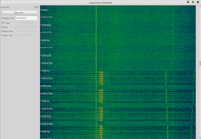
    I got a little help on Reddit. Thanks to PE1NUT for identify a way to visualize the crystal drift in the data and jddes for doing some sleuthing: he identified some On Off Keying (OOK) right at ignition. Sure enough; I loadded the data up in Inspectrum (which I should have done in the first place!):


    Turns out Paul is using a 900 MHz wireless transmitter to ignite the rocket which sends OOK for about 1.5 seconds, which leave its mark at 1.5 GHz! There are peaks at ~ -300kHz and ~ +650kHz.

    So I played around with filtering the data with mixed success initially. When you look at the data, the intermediate frequency (IF) is 110 Hz, or damn near zero, so half the spectrum is negative in frequency and the other half is positive. In order to filter just one half of the spectrum you need to have complex taps on your FIR filter. Now, the problem is most of the GNURadio filter blocks don't expose complex taps! The generic FIR filter and the band pass filter do but you have to provide the taps. Fair enough... but the gui to firdes (Finite Impulse Response Design tool) doesn't expose complex taps either! Ideally we'd want two band reject or notch filter. But since the band pass filter does work with complex taps we can add (n+1) band pass filters together to do the same thing - we just band pass two chunks instead of band rejecting one. Ultimately the flowgraph looks like this:


    I also put in an automatic gain control block to try and deal with the jumps in the spectrum (horizontal lines). You can download the flowgraph if you like.

    The easiest way to just filter a chunk of time is to split up the data file into three - the first part, the noisy part, and the last part. A combination of "split -b" and "head -c" are used on the command line, then the files are re-merged with CAT.

    Here's the cleaned-up spectrum. There's still some jumps in the spectrum but the peaks are nulled out. We lose data, but the hope is that the data lost is outweighed by the interference removed.


    I still don't get a valid fix during engine firing but I do reacquire satellites a bit quicker... meaning more data in flight!  Updated trendline in black. Tracking from ~ 3500m to 5000m, covering 12 seconds of flight. There are 30 seconds from ignition to apogee, gnss-sdr loses lock during motor firing (~6 seconds) assuming that is insurmountable there is a maximum of 18 seconds of valid GPS data. Assuming perfection, you could start tracking on the next subframe and have a maximum of 20 seconds of flight data, (if you miss that subframe, 15 seconds) so we're over halfway there. Of course, not losing it during the motor firing would be ideal!

    Money shot

    Tuesday, April 5, 2016

    Paul Breed Rocket Flight Test Data #2: PROGRESS!

    I GOT A gnss-sdr PVT SOLUTION IN FLIGHT!

    Success kid is successful.

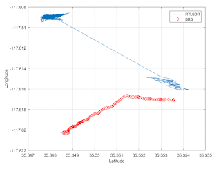
    So I managed to get a valid navigation solution for ~ 7 seconds in flight close to what I presume is apogee, absent additional information. Paul flew an IMU but lost the SD card and a Big Red Bee GPS tracker which is, of course, subject to CoCom limits. Below I plotted both the RTLSDR (in red) and the Big Red Bee (in yellow... in retrospect this should have been red!)


    I removed spurious readings from the GPS tracker: these are easy to identify because the GPS time is out of sync. The long red and yellow lines connect the dots from the last good reading on the pad to the first good reading in flight, and are not representative paths per see. If we assume data to be correct it appears the RTLSDR acquires a navigation solution at a higher altitude than the BRB, which based on the speed and drift is operating under chutes. Next up I extracted the the lat/lon/alt from the PVT solution generated by GNSS-SDR (again, the blue line is just connecting the last good fix on the pad with  the first good fix in flight). The data is aligned with the last good fixes for both the RTLSDR and BRB. 


    Now we get confirmation that the RTLSDR does indeed acquire before the BRB, and a little mental extrapolation can connect the dots between the last RTLSDR sample and the first BRB sample post-launch if we presume the rocket is drifting steadily under a drogue parachute. (The inflection in the BRB is likely going from drogues to main chute - awaiting confirmation.)

    The rocket pops the nosecone at apogee to deploy a drogue chute, at which time the nosecone is swinging in the breeze and we don't anticipate getting any data from the RTLSDR because the directional antenna is no longer pointed up. However the BRB is expected to get a fix under chutes, when within the CoCom limits. My thesis is that we get a valid GPS solution about 7 seconds before popping the nosecone and deploying the drogue, which then causes us to lose track on most of the satellites and thus lose our navigation solution. Indeed, the rest of the flight is filled with messages of acquiring and subsequently losing acquisition of satellites.

    Here's an excerpt of the output from just before liftoff to just after apogee:
    Current input signal time = 145 [s]
    NAV Message: received subframe 3 from satellite GPS PRN 22 (Block IIR)
    NAV Message: received subframe 3 from satellite GPS PRN 31 (Block IIR-M)
    NAV Message: received subframe 3 from satellite GPS PRN 1 (Block IIF)
    NAV Message: received subframe 3 from satellite GPS PRN 14 (Block IIR)
    NAV Message: received subframe 3 from satellite GPS PRN 3 (Block IIF)
    NAV Message: received subframe 3 from satellite GPS PRN 10 (Block IIA)
    NAV Message: received subframe 3 from satellite GPS PRN 25 (Block IIF)
    Position at 2016-Feb-06 18:45:47 UTC is Lat = 35.34828164793844 [deg], Long = -117.8089714500355 [deg], Height= 646.4366382388398 [m]
    Current input signal time = 146 [s]
    Position at 2016-Feb-06 18:45:48 UTC is Lat = 35.34792485975112 [deg], Long = -117.8090110485498 [deg], Height= 653.1580742103979 [m]
    Current input signal time = 147 [s]
    Position at 2016-Feb-06 18:45:49 UTC is Lat = 35.34836233536886 [deg], Long = -117.8087743892498 [deg], Height= 622.0710280425847 [m]
    Current input signal time = 148 [s]
    Position at 2016-Feb-06 18:45:50 UTC is Lat = 35.34776621261069 [deg], Long = -117.8090573844694 [deg], Height= 649.063727453351 [m]
    Current input signal time = 149 [s]
    Position at 2016-Feb-06 18:45:51 UTC is Lat = 35.34842555835016 [deg], Long = -117.8087875236563 [deg], Height= 634.0006730658934 [m]
    Current input signal time = 150 [s]
    Position at 2016-Feb-06 18:45:52 UTC is Lat = 35.34802741910629 [deg], Long = -117.808877076439 [deg], Height= 641.1753705441952 [m]
    Current input signal time = 151 [s]
    NAV Message: received subframe 4 from satellite GPS PRN 22 (Block IIR)
    NAV Message: received subframe 4 from satellite GPS PRN 10 (Block IIA)
    Loss of lock in channel 5!
    Tracking start on channel 5 for satellite GPS PRN 11 (Block IIR)
    Current input signal time = 152 [s]
    Loss of lock in channel 6!
    Loss of lock in channel 3!
    Tracking start on channel 6 for satellite GPS PRN 31 (Block IIR-M)
    Tracking start on channel 3 for satellite GPS PRN 14 (Block IIR)
    Loss of lock in channel 0!
    Tracking start on channel 0 for satellite GPS PRN 1 (Block IIF)
    Loss of lock in channel 4!
    Tracking start on channel 4 for satellite GPS PRN 22 (Block IIR)
    Current input signal time = 153 [s]
    Loss of lock in channel 5!
    Tracking start on channel 5 for satellite GPS PRN 11 (Block IIR)
    Loss of lock in channel 6!
    Tracking start on channel 6 for satellite GPS PRN 31 (Block IIR-M)
    Loss of lock in channel 3!
    Tracking start on channel 3 for satellite GPS PRN 14 (Block IIR)
    Loss of lock in channel 0!
    Tracking start on channel 0 for satellite GPS PRN 1 (Block IIF)
    Loss of lock in channel 4!
    Tracking start on channel 4 for satellite GPS PRN 22 (Block IIR)
    Current input signal time = 154 [s]
    Current input signal time = 155 [s]
    Loss of lock in channel 4!
    Tracking start on channel 4 for satellite GPS PRN 22 (Block IIR)
    Current input signal time = 156 [s]
    Current input signal time = 157 [s]
    Loss of lock in channel 4!
    Tracking start on channel 4 for satellite GPS PRN 22 (Block IIR)
    Current input signal time = 158 [s]
    Current input signal time = 159 [s]
    Current input signal time = 160 [s]
    Current input signal time = 161 [s]
    Current input signal time = 162 [s]
    Current input signal time = 163 [s]
    NAV Message: received subframe 1 from satellite GPS PRN 11 (Block IIR)
    NAV Message: received subframe 1 from satellite GPS PRN 14 (Block IIR)
    Current input signal time = 164 [s]
    Current input signal time = 165 [s]
    Current input signal time = 166 [s]
    Current input signal time = 167 [s]
    Current input signal time = 168 [s]
    Current input signal time = 169 [s]
    NAV Message: received subframe 2 from satellite GPS PRN 11 (Block IIR)
    Current input signal time = 170 [s]
    Current input signal time = 171 [s]
    Current input signal time = 172 [s]
    Current input signal time = 173 [s]
    Current input signal time = 174 [s]
    Current input signal time = 175 [s]
    NAV Message: received subframe 3 from satellite GPS PRN 1 (Block IIF)
    NAV Message: received subframe 3 from satellite GPS PRN 11 (Block IIR)
    NAV Message: received subframe 3 from satellite GPS PRN 14 (Block IIR)
    NAV Message: received subframe 3 from satellite GPS PRN 3 (Block IIF)
    Current input signal time = 176 [s]
    Position at 2016-Feb-06 18:46:18 UTC is Lat = 35.3536423978743 [deg], Long = -117.8154004936006 [deg], Height= 4891.649443297647 [m]
    Current input signal time = 177 [s]
    Position at 2016-Feb-06 18:46:19 UTC is Lat = 35.35313826705141 [deg], Long = -117.8151172574466 [deg], Height= 4786.770911485888 [m]
    Current input signal time = 178 [s]
    Position at 2016-Feb-06 18:46:20 UTC is Lat = 35.35361800624526 [deg], Long = -117.8156283909009 [deg], Height= 4907.156536793336 [m]
    Current input signal time = 179 [s]
    Position at 2016-Feb-06 18:46:21 UTC is Lat = 35.35351364315449 [deg], Long = -117.815566988265 [deg], Height= 4801.439769400284 [m]
    Current input signal time = 180 [s]
    Position at 2016-Feb-06 18:46:22 UTC is Lat = 35.35325156470748 [deg], Long = -117.8156706709576 [deg], Height= 4741.917847431265 [m]
    Current input signal time = 181 [s]
    NAV Message: received subframe 4 from satellite GPS PRN 22 (Block IIR)
    NAV Message: received subframe 4 from satellite GPS PRN 1 (Block IIF)
    NAV Message: received subframe 4 from satellite GPS PRN 31 (Block IIR-M)
    NAV Message: received subframe 4 from satellite GPS PRN 11 (Block IIR)
    NAV Message: received subframe 4 from satellite GPS PRN 3 (Block IIF)
    Loss of lock in channel 7!
    Current input signal time = 182 [s]
    Tracking start on channel 7 for satellite GPS PRN 23 (Block IIR)
    Loss of lock in channel 3!
    Tracking start on channel 3 for satellite GPS PRN 26 (Block IIF)
    Current input signal time = 183 [s]


    Therefore, based on the output and plots, I believe liftoff takes place at 151 seconds, engine burns for ~ 5-6 seconds (highlighted in yellow), with apogee occurring at 182 seconds, or roughly 30 seconds on ascent. Apogee of ~ 4850 meters ASL.

    The numerous subframes from 163-182 seconds show we are still getting some meaningful data which could be interpreted by a fft-based approach like fastpgs.


    So what did you change?

    I lowered the bandwidth of all 3 tracking loops by roughly half. Previously I had increased the bandwidth on the loops figuring more bandwidth = ability to deal with rapid shifts in phase/frequency but my intuition was incorrect. I'm still a DSP newbie but I am learning.

    To Do
    1. Continue playing with tracking loops 
    2. Investigate fastgps fft-based solutions

    Files
    1. BRB.kml - Big Red Bee GPS Logger
    2. RTLSDR.kml - RTLSDR tracking

    Saturday, April 2, 2016

    Paul Breed Rocket Flight Test Data!

    This post is long overdue as I've been quite busy with my day job that I've been remiss in updating the blog with the progress happening with the rocket GPS.

    On February 6th, 2016 Paul Breed flew an RTL-SDR on a high power rocket to capture GPS RF data for post-processing. This was the second test flight and the first one to get good data.

    Hardware Configuration

    Paul shows off the payload. The blue box outlines a 6DOF IMU, the orange box is a LNA4ALL low noise amplifier. On the reverse the orange box outlines a 2S LiPo battery, the green box a Nooelec 0.5PPM TXCO in aluminum case and the blue box an Intel Compute Stick running Ubuntu, and the yellow trapezoid a quadrifilar antenna GPS antenna from antennas.us.


    Backside of RF capture unit.


    Frontside of RF capture unit.


    Hardware Configuration

    They payload is packaged inside the nosecone fairing of the rocket. Here, the rocket is mounted on the launch rail in a horizontal configuration. Before launch the rail is elevated to near vertical, but this orientation allows for easy handling of the rocket.

    Rocket mounted on the launch rail

    At T-2 minutes (2 minutes prior to launch) the rocket begins aquiring data - Paul SSH's over wifi into the Intel Compute Stick to trigger a script which calls rtl_sdr centered on the L1 frequency with a bandwidth of 2048000 Hz. Two minutes is sufficient time to get multiple GPS fixes of the launch site.

    And at T-0, smoke and flames!

    Liftoff!


    Post-flight analysis

    I took the output from rtl_sdr and converted it to complex for gnss-sdr. I was able to get a fix on the pad but not much after that. The last fix was at about 145 seconds - liftoff was likely between 145 and 150 seconds. I attempted to make a few tweaks to the tracking loop configuration gnss-sdr file with little success - it changed the results but not the actual character, that is not a whole lot after liftoff. I did find I was able to get a few subframes well after launch - 3 with the final configuration file - but not enough to get a fix. But there are other codes to be investigated which can get an approximate fix without a full 4 satellite solution.

    One of the productive changes was decreasing the step size of the doppler search - this performs a more refined search and reveal more post-launch subframes. Initially I had one subframe and through tweaking the search step size (to 100 hz) I was able to get three. It is tempting to increase the doppler window but the max doppler shift of a GPS satellite to a stationary receiver is ~ 5kHz and the default search window is +/- 10 kHz - unless you are going orbital velocity at the satellite while it is coming at you, you are well within 10 kHz.

    Here's the KML file in Google Earth. Don't get too excited about the altitude jumps! There are two of them in the file one occurs during the first few fixes and the last ones are of similar magnitude. I've seen the same thing happen with fixes at home. We know for the early jumps the rocket is sitting soundly on the pad and the latter jump is of the same magnitude.


    I took the GPS time from gnss-sdr and used an online tool to back out the orientation of the satellite constellation during the rocket flight. The arrows point to the satellites which were used to get position fixes as output in the RINEX files. It is interesting to see some satellites which appear farther away on the map are useful to getting a fix where closer ones are not - however that's only half the story.


    If we look at altitude (the earth is crudely pointed so the launch site is oriented up towards the top of your monitor) we see the satellites it uses are largely overhead and the "closer" satellites are on the horizon.


    I also looked at the two satellites which gave valid subframes after T-0, they are PRN 3 and PRN 11, shown here.


    So why didn't we get a good fix in flight? There are two likely culprits - the vibration / acclereation environment and the loop dynamics. Both vibration and acceleration affect the crystal which effects the frequency being captured. If the tracking loops are off then we'd anticipate losing satellite  directly overhead (in the direction of acceleration) and not laterally where the acceleration of the rocket doesn't effect things much. I tweaked the tracking loops as far as I could without making results worse and they didn't seem to get any better. Based on the fact that one of the satellites is fairly high in the sky my gut suspects the acceleration/vibe environment.

    UPDATE: Got a brief in-flight nav solution; see this post!

    But there's still work to be done to try fft-based approaches like fastgps, dig into the intermediate outputs and see if some smart people out there have ideas!

    Thanks to Paul for providing the data, test hardware and ideas on how to look at and understand the data. Follow his blog or twitter!
    Files
    1. Feb6.bin - raw RTLSDR binary file (interleaved shorts) you will need to convert to complex.
    2. flight.conf - gnss-sdr configuration file
    3. output.log - Console output from "gnss-sdr --config_file=flight.conf"
    4. PVT.kml - Position fixes in Google Earth format
    5. GSDR086x11.16N - Navigation data in RINEX format 
    6. GSDR086x11.16O - Observation data in RINEX format

    Next Actions
    1. Investigate gnss-sdr telemetry and tracking outputs
    2. Try running through fastgps code 
    3. Get help from smart gps/sdr folk!

    Sunday, March 6, 2016

    An RTL-SDR dataset for gnss-sdr

    I've had several requests for a dataset for users to play with. I've been recalcitrant simply because every dataset I've taken has been from my house! So this week I went to a park and took a two-minute acquisition using GNSS-SDR. My setup is a RTL-SDR stick with a 0.5PPM TXCO and aluminum case with the bias tee mod, a LNA4ALL, and a cheap active GPS antenna. (By no means are 0.5PPM TXCO, aluminum care or LNA4ALL requirements, I've gotten a good fix with a cheap dongle in a plastic case with no LNA.)

    The dataset lives on my Google Drive. The .conf file is the file I used for acquisition. If you want to use it for playback with gnss-sdr, you need to make the following changes

    Line 29: Change the SignalSource.implementation from Osmosdr_Signal_Source to File_Signal_Source
    Line 30: Uncomment the SignalSource.filename and provide the correct path to the data file
    Line 42: Change SignalSource.dump to false

    gnss_sdr_pvt.nmea contains position/velocity/time (PVT) in NMEA format. The GSDR063p40.16N contains the raw navigational information and the GSDR063p40.16O contains the observables. PVT.kml is a Google Earth file with coordinates.

    You might be interested in recovering the chip rate.

    Saturday, February 27, 2016

    Find the signal in the noise


     GPS signals are very weak, coming in at about 120 dBm ... which is below the thermal noise floor of ~ 100 dBm! If you try plotting an FFT 2 MHz wide about the L1 frequency you won't be able to distinguish the signal from the noise.


    But it is there, and we can find it! 

    First, we need data. I used data collected with an RTL-SDR stick converted to complex output. The output from the RTL-SDR is interleaved unsigned short, whereas the input block expects signed complex numbers. I talked about this in a prior post; I use the gcc code myself. 

    So when we have data we can build a very simple flow diagram in GNURadio to play back the file and visualize it using the Fast Autocorrelation Sink. As noted in a previous post, there is a bug in GNURadio which breaks the Fast Autocorrelation Sink, but it is an easy fix!


    The Fast Autcorrelation Sink is documented on Balint Seeber's blog and provides links to why the fast autcorrelation sink is indeed so fast! If you aren't familiar with autocorrelation, it is the correlation of a signal with itself. At any given time the correlation of a signal with itself is perfect, but if you insert a time delay and look at a later signal compared to a previous signal we can see just how similar the later signal. 

    For example let's visualize a triangle wave with a frequency of 1000 Hz - that is, 1000 peaks per second, or 1 peak per millisecond. Since each repetition of the triangle is exactly 1 millisecond apart and since there is no noise in the system we would expect that every millisecond we'd have a perfect correlation of the shifted signal to the current signal. In between those milliseconds the correlation would get worse until we were half a millisecond apart where the peaks from the original signal would line up with the troughs of the shifted signal, resulting in a negative correlation.

    Here's a simple flowgraph in GNURadio to visualize the autocorrelation using the Fast Autocorrelation Block from gr-baz. First, we create a signal source of a triangle wave with a frequency of 1000 Hz. Then we insert a throttle - this throttles the rate at which the diagram runs so we can visualize the signal. Left to its own devices GNURadio would simply pump triangle waves as quickly as it could with the given CPU resources. Then we can visualize the waveform using a WX GUI signal sink and the autocorrelation using the Fast Autocorrelation Sink:


    Note the color of the block interfaces: Orange. This means floating point. Most of the blocks will default to complex, which is what you'd want for a lot of radio work but in this case it just makes things confusing as you will be plotting the triangle waves in both the Re and Im space. You can double click on each block and change the types to floating point or POWERUSER TIP: Click on the block and use up/down arrows to change the type. Once the flowgraph is complete (or download it here) hit play and you should see something like this:


    We see our triangle waves with a period of 1 Hz and the Fast Autocorrelation Sink showing peaks at 1 Hz, and negative peak at a rate of 1 Hz shifted by half a Hz. 

    So now let's do it with a real signal. You can use the same flowgraph, we just need to substitute the signal source block for a file source and specify our complex file. And since the file is complex, we need to change the data types. Finally, the throttle should be set to the sample rate of your input source - in my case, 2048000 Hz for the RTL-SDR. For the fast autocorrelation sink you will likely want to tweak the size to make the number of milliseconds a reasonable number. For my use I did (2**18)/2. Here's the updated diagram, running with the Fast Autocorrelation Sink, which you can download from github.


    We see nice peaks every millisecond. Why every millisecond?

    The coarse/acquisition code for GPS (C/A) has a period of 1023 chips which are transmitted at a rate of 1.023 MBit/s. This results in period of 1 millisecond. BAM! You can read more about the encoding on wikipedia. The L1 carrier at 1575.42 MHz has two codes, the C/A code and the navigation message. The navigation message varies with time as the satellites move through space but the C/A code does not change.  The C/A code is used for locking onto the satellites: Each satellite has a different unique C/A code. Earthside a receiver generates a particular C/A code and then shifts it in time and frequency to correlate the known C/A code with the C/A code of the satellite. Since we don't have a perfect clock we have to shift in time to line up our signal with the GPS signal timing and since the satellites are moving rapidly they frequency we receive is subject to a doppler shift of up to 5kHz (10kHz if we are moving very quickly, say, on a rocket or missile)

    But that's a story for another day.